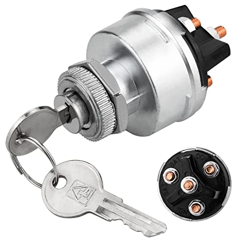
In automotive wiring, a 4-wire ignition switch is the most common type of switch used. It has four terminals: “R”, “B”, “T”, and “S”. The “R” and “B” terminals are connected to the battery, while the “T” and “S” terminals are connected to the starter.
The ignition switch is an important part of the engine system. It is responsible for turning on the engine and allowing it to run.
There are several different types of ignition switches, but the most common is the 4 wire ignition switch. In this article, we will discuss the 4 wire ignition switch diagram and how to use it.


A 4-wire ignition switch is a type of ignition switch that is used in many Motorcycles, cars and trucks. It is commonly found on vehicles made by Ford, Chevy, Dodge, and Jeep.
It consists of two leads connected to the engine block: a black lead for the cranking coils and a red lead for the firing coils. When you turn the key to the on position, current flow from the battery through both leads to the spark plugs.
What Is An Ignition Switch?

An ignition switch is a component of an automotive engine that controls the spark plugs and starts the engine. The switch is typically a 4-wire design with two terminals (usually blue and yellow) and two armatures.
When the key is turned to the on position, current travels through both armatures, initiating a spark at the plug.
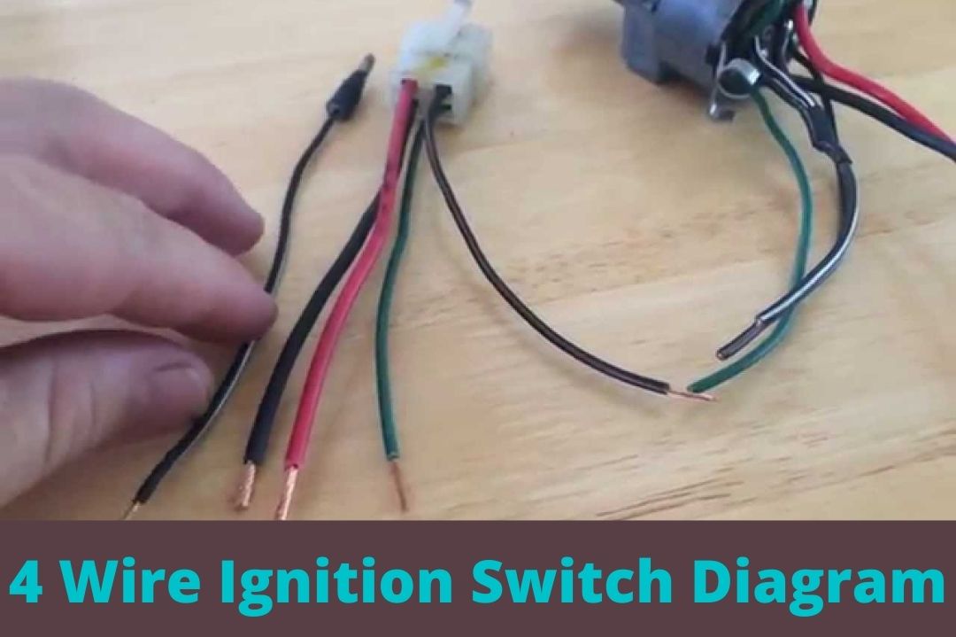
4 Wire Ignition Switch Diagram:
There are four wires that run from the ignition switch to the engine. These are the white wire, the black wire, the red wire, and the green wire.
The white wire is always hot, and it goes to the distributor. The black wire is always ground, and it goes to the battery.
The red wire is used for turning on the lights, and it goes to a light switch in your car. The green wire is used for starting your engine, and it goes to your starter motor. This is the 4 wire scooter ignition switch diagram that may be helpful to wire ignition switch.
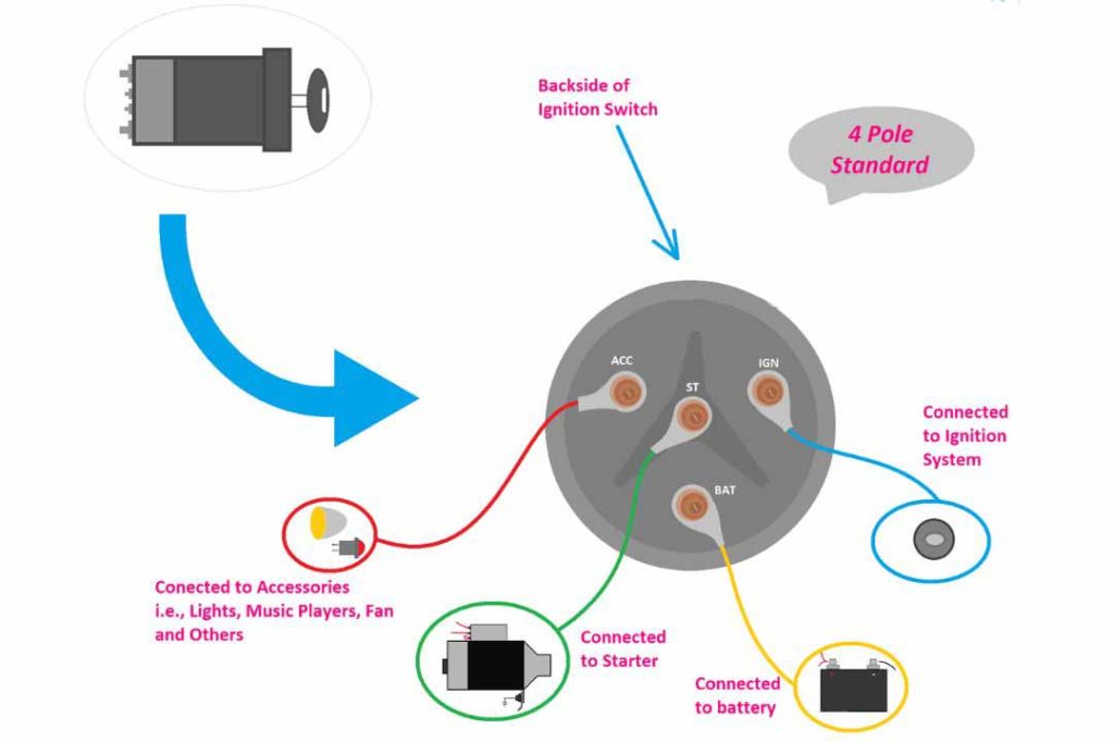
4 Wire Ignition Switch Color Code
Here is the exact 4 wire ignition switch color code:
- BAT (battery) – Red
- IGN (ignition) – Yellow or Red
- ST (starter) – Brown or Yellow
- ACC (accessory) – Purple
The BAT wire is the thickest wire and is always energized. It provides power to the ignition switch and the rest of the electrical system. The IGN wire is the primary terminal that controls the ignition and other electronics.
The ST wire connects to the starter solenoid and provides power to the starter motor when the ignition switch is turned to the start position. The ACC wire sends power to the accessories on the car, such as the lights, radio, and windshield wipers.
It is important to note that the wire color codes may vary depending on the manufacturer of the vehicle. However, the BAT, IGN, ST, and ACC wires are the most common wires found on a 4 wire ignition switch.
Here is a table that summarizes the 4 wire ignition switch color code:
| Wire | Color | Function |
|---|---|---|
| BAT | Red | Battery |
| IGN | Yellow or Red | Ignition |
| ST | Brown or Yellow | Starter |
| ACC | Purple | Accessory |
How To Wire A 4 Wire Ignition Switch?
As shown in 4 wire motorcycle ignition switch diagram this is used on a number of different makes and models of vehicles. It features two sets of wires that are connected to the points at the front and rear of the engine.
When you turn the key to the “on” position, current flows through both sets of wires. This causes a spark in the engine and starts it running.
Ascertain the Terminals On Ignition Switch:
The ignition switch is a four-wire device that controls the engine in a car. The black (hot) wire is connected to the battery and goes to the starter motor.
The white (neutral) wire goes to the vehicle’s electrical system and the green (ground) wire goes to the chassis.
Disconnect the Terminals:
There are typically four terminals on an ignition switch. Two are black and two are red. To disconnect the terminals, first remove the screws that hold the switch cover in place. Then, pull out each terminal.
More: How To Hot Wire A 4 Wheeler?
Disassemble The Steering Wheel:
There are several screws that hold the steering wheel in place. Remove these screws and then pull the wheel off of the column. There are three wires that attach the wheel to the column: black, red, and green.
Put Keys in the Right Position:
When starting a car, it is important to keep the keys in the right position. This means that the ignition switch should be in the “On” position. If the keys are not in the right position, it will not start the car.
Release the Pins:
The ignition switch is a component of the car that is used to turn on the engine. It has 4 wires running through it.
When you turn the key to the ‘on’ position, the pin in the switch that corresponds with the wire closest to the key turns on, and sends a current down that wire. The other pins stay off because they don’t have a current going through them.
Check the Wires:
The first step in troubleshooting a 4-wire ignition switch is to check the wires. To do this, you need to remove the cover plate on the switch and access the wires.
Take a look at each wire and make sure it is properly connected to its respective terminal.
More: How To Start A Quad Without A Key?
Connect the Accessory And Starter Relay Wire:
The accessory and starter relay wire connects to the ignition switch on the car. The black wire connects to the negative terminal of the battery, and the red wire connects to the positive terminal.
Attach Ignition Wire And Reinstall The Switch:
When replacing your ignition switch, it’s important to first attach the wire. This is done by threading the wire through the hole in the cover and then tightening the screw on either side of it.
Make sure that both ends of the wire are securely fastened before reinstalling the cover. Once you’ve attached the wire, take a look at your switch.
You may need to replace it if it’s damaged or if there’s something blocking its operation. If so, remove the old switch and install a new one in its place. Be sure to tighten all of the screws before reinstalling the cover.
More: How To Hot Wire A Mongoose 90?
Test The Switch And Reassemble the parts:
If the switch is not working, it is important to test it. Testing the switch means turning the key to the accessory position and checking for power to the headlight.
If power is not present, then the switch may be bad and needs to be replaced. After testing the switch, it is important to reassemble the parts in order for them to work properly.
Honda 4 Wire Ignition Switch Diagram
A Honda 4 wire ignition switch diagram is a wiring diagram that shows the connections of the 4 wires that are typically found on a Honda ignition switch.
The ST wire connects to the starter solenoid and provides power to the starter motor when the ignition switch is turned to the start position. The ACC wire sends power to the accessories on the car, such as the lights, radio, and windshield wipers.

The wires are typically color-coded, and the diagram will show the color of each wire and its function. The diagram will also show the location of the wires on the ignition switch.
The 4 wires on a Honda ignition switch are:
- BAT (battery) – Red
- IGN (ignition) – Yellow or Red
- ST (starter) – Brown or Yellow
- ACC (accessory) – Purple
The BAT wire is the thickest wire and is always energized. It provides power to the ignition switch and the rest of the electrical system. The IGN wire is the primary terminal that controls the ignition and other electronics.
The Honda 4 wire ignition switch diagram is a valuable tool for anyone who needs to troubleshoot or repair a Honda ignition switch. The diagram can help you to identify the correct wires and their functions, which can make troubleshooting much easier.
Here Are Some of The Uses of A Honda 4 Wire Ignition Switch Diagram:
How Does A 4-Wire Ignition Switch Work?
A 4-wire ignition switch is a type of automotive switch that uses four wires to send power from the battery to the engine. These switches are usually located on the dashboard or within easy reach of the driver.
When you turn the key in the ignition, power travels from the battery through the IGN (ignition) wire and then to each of the other three wires.
How To Install A 4-Wire Ignition Switch In Your Vehicle?
Installing a 4-wire ignition switch in your vehicle is a simple process that can save you time and hassle. Follow these steps to get the job done:
What Color Wire Is The Ignition Wire?
Most vehicles have four wires that are used to initiate the start of the engine- yellow, green, brown, and red. These wires are usually color coded according to their function.
The yellow wire is usually used to turn on the ignition switch, the green wire is used for ground (or a reference), the brown wire is used for power (usually +12 volts), and the red wire is used for signal (usually 0 volts).
What Wires Go to Ignition Switch?
Ignition Wire (yellow or Red): This wire is the primary terminal that controls the ignition and other electronics.
In addition to these four wires, there may be other wires that go to the ignition switch, such as a wire for the security system or a wire for the cruise control. The exact number and color of wires will vary depending on the vehicle.
Conclusion: 4 Wire Ignition Switch Diagram:
Now that you know how a 4-wire ignition switch works, you’re ready to install one in your car. Be sure to follow these simple steps to ensure a successful installation. In conclusion, knowing how to wire an ignition switch is a very handy skill to have.
It can come in handy in a variety of situations, from fixing a broken ignition switch to wiring a new one into your car.
FAQs
How Does A 4 Wire Ignition Switch Work?
A 4 wire ignition switch is a simple electrical circuit that is used to start a car. When the key is turned to the “on” position, current flows through the black and brown wires. The red wire is not used in this type of switch and does not contribute to starting the car.
How Do You Wire A 4 Wire Ignition?
There are four wires that go into a 4-wire ignition system. The black (hot), brown (neutral), green (ground), and blue (positive) wires. The black wire is always hot, the brown wire is always neutral, the green wire is always ground, and the blue wire is always positive.